What Is a Single Stage Pump and How Does It Work?
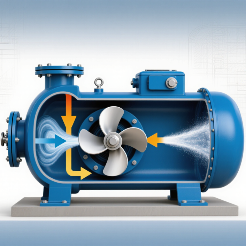
A Single Stage Pump uses one impeller to transfer liquid from the suction side to the discharge side. Its design is comparatively simple. Liquid enters the casing, reaches the rotating impeller, and gains velocity. The casing then converts much of that velocity into pressure. In practical terms, picture water entering through a pipe, turning around the impeller, and leaving at a higher pressure.
This operating principle explains why single-stage designs remain common in water supply, irrigation, HVAC circulation, and general industrial service. The U.S. Department of Energy reports that pumping systems can consume 25% to 50% of industrial facility electricity. That figure includes many pump types, not only single-stage units. Still, it shows why correct sizing matters. A pump that is too large may waste energy through throttling. A pump that is too small may run continuously and fail to meet demand.
The Hydraulic Institute emphasizes selecting pumps according to duty point, efficiency, materials, and operating conditions. Those details include flow rate, total head, liquid temperature, viscosity, and possible solids. Experience at the installation site also matters. A clean-water pump may struggle with abrasive fluid. A technically correct model can still perform poorly with poor pipe design, air leaks, or frequent starts.
This guide explains how a Single Stage Pump works, what its main components do, and where its limits appear. It also examines efficiency, maintenance, and selection practices. Market reports often combine centrifugal and industrial pump categories, so their figures require careful interpretation. That limitation deserves attention. Simple explanations help, but real pump performance depends on measured conditions, not marketing claims.
Definition and Core Purpose of a Single-Stage Pump
A single-stage pump is a machine with one impeller that moves liquid from one location to another. Its core purpose is to create flow and provide useful pressure for a system. The pump does not usually increase pressure in several internal steps. Instead, one rotating impeller transfers energy directly to the liquid.
In a common centrifugal design, liquid enters through the suction opening near the impeller center. The motor turns the impeller at high speed. Curved blades push the liquid outward, increasing its velocity. The casing then guides that liquid toward the discharge opening. As velocity changes inside the casing, part of it becomes pressure. This process supports water circulation, irrigation, cooling equipment, and many industrial services.
The definition sounds simple. Real operation is less forgiving. Air in the suction line can interrupt flow, while a blocked strainer can reduce performance. Incorrect pipe sizing may create noise, vibration, or unstable pressure. I have found that many pump problems begin outside the pump itself. The liquid’s temperature, viscosity, and cleanliness also affect selection. A single-stage pump may work efficiently, but only within its designed flow and pressure range. That limitation matters. Checking operating data, alignment, seals, and bearing condition helps confirm whether the pump is doing its intended job. Even a small leak deserves attention, although it may not immediately stop the system.
What Is a Single-Stage Pump and How Does It Work?
A single-stage centrifugal pump uses one impeller to convert motor energy into fluid pressure and flow. As flow increases, the available head typically decreases, while hydraulic power rises until the pump approaches its practical operating limit.
The chart presents a representative head–flow relationship at a constant rotational speed. Hydraulic power is calculated using P = ρgQH, assuming water density of 1,000 kg/m³ and gravitational acceleration of 9.81 m/s².
How a Single-Stage Pump Moves Fluid
A single-stage pump uses one impeller to move fluid from a low-pressure area to a higher-pressure discharge line. In many industrial systems, the impeller spins inside a casing, creating centrifugal force. Fluid enters through the suction opening near the impeller’s center. The rotating blades then push it outward at high speed.
The casing slows the fluid and converts part of its velocity into pressure. A volute-shaped passage guides the flow toward the outlet. The result? Continuous movement through pipes, filters, or process equipment. Before operation, the pump usually needs proper priming. Air inside the suction line can prevent the impeller from developing enough pressure.
In field inspections, I check the suction pipe, valve position, and fluid level before judging pump performance. A restricted inlet may cause vibration, noise, or cavitation, where vapor bubbles form and collapse near the impeller. That damage can appear gradually, not dramatically. Flow rate also depends on pipe length, elevation, fluid thickness, and system resistance. A pump that performs well on a test bench may behave differently in a crowded plant. It is easy to oversimplify the process. Real installations rarely behave perfectly. Careful measurements of pressure, temperature, vibration, and flow provide a more reliable picture of how the pump is moving fluid.
Common Types and Operating Configurations
A single-stage pump uses one impeller to transfer liquid from suction to discharge. The impeller adds velocity, while the casing converts much of that velocity into pressure. This design suits clean water, cooling fluids, irrigation, and many light industrial duties. It is simpler than a multistage pump, but it cannot create the same high head.
Common types include end-suction centrifugal pumps, inline pumps, and split-case pumps. End-suction models are compact and widely used for general service. Inline designs fit directly into vertical pipework, saving floor space. Split-case pumps often support larger flow rates and easier maintenance access. Operating configurations also matter. A horizontal arrangement usually simplifies inspection. A vertical arrangement can reduce space requirements. Pumps may run alone, in parallel for changing demand, or in series for higher pressure.
The U.S. Department of Energy reports that pumping systems can represent about 25% of industrial electricity consumption. Correct configuration therefore affects energy use, not only installation cost. Parallel pumps can improve flexibility, but poor control may cause short cycling. Series operation increases pressure, yet seals and pipework face greater stress. Field conditions often challenge neat calculations.
Tips
Check the duty point against real flow and head data. Measure suction pressure, discharge pressure, vibration, and motor load. Keep it practical. The “best” arrangement may still need adjustment after commissioning. Even a small mismatch can create noise, heat, or unnecessary energy consumption. Review the U.S. DOE pumping-system guidance and Hydraulic Institute testing practices before final selection.
Typical Applications, Benefits, and Limitations
What Is a Single Stage Pump and How Does It Work?
Typical Applications, Benefits, and Limitations
A single stage pump uses one impeller to move liquid and create pressure. Liquid enters through the suction port and reaches the rotating impeller. The impeller adds velocity, while the casing converts much of that velocity into pressure. This design is common in centrifugal pumping systems.
Typical applications include building water supply, irrigation, drainage, cooling circuits, and light industrial transfer. In a small workshop, one pump can move clean water between a storage tank and a process line. Maintenance is usually straightforward because the internal structure is relatively simple. Fewer parts can also reduce purchase and repair costs. Performance is often efficient when the pump operates near its designed flow rate.
However, a single stage pump has practical limits. It may not provide enough head for tall buildings, long pipelines, or high-pressure processes. A multistage design may suit those conditions better. Operation outside the recommended range can cause vibration, overheating, or cavitation. Dirty, abrasive, or highly viscous liquids may also require a different pump configuration.
The simple design is not automatically the best choice. I have seen systems selected by flow rate alone, even when available suction conditions were poor. That mistake can shorten service life. Engineers should check fluid properties, required head, temperature, pipe losses, and duty-cycle changes before choosing the pump. Field conditions often differ from the original calculation. Testing and periodic inspection still matter.
